
Developing a ROS2 Quadruped — GUIs, Gaits, and Forward Kinematics
Building a four-legged walker with ROS2: steppers + 8 servos on a Raspberry Pi, a Tkinter GUI that renders the robot from real forward kinematics, and a record/playback loop that turns gaits into data instead of code.
The problem with "just write gait constants"
A walking robot has one sneaky property: its gait lives somewhere between hard engineering and choreography. Too many leg projects hard-code arrays of servo angles in the firmware, and then every mechanical change — a longer leg, a stripped gear, a new bracket — turns a tune into a recompile. This project's goal was the opposite: make a gait a recording you can tweak with your mouse.
The walker itself is split in two halves (stepper + servo), because the hardware demands it:
- Stepper motors do the coarse locomotion — two 4-wire steppers, step sequences driven straight off GPIO.
- Eight servos articulate the four legs (upper + lower per leg).
And the software is split the same way, but along transport lines so each half can develop independently.
ROS2: one topic, two packages
The design that made this project work is the boundary between two ROS2 Humble packages:
- robot_controller — owns the hardware. It subscribes to a single
robot_commandtopic and interprets a tiny text protocol:'L'/'R'→ rotate a stepper 512 steps,'S1:90'→ move one servo to an angle,"A 90;B 45;C 120;…"→ move several servos at once (the GUI's bread and butter).
- robot_interface — the human side. A Tkinter app that publishes to that same topic and renders the robot as it responds.
Because there is no shared memory, only a topic, the two packages never have to run on the same machine: the GUI can sit on a laptop while controller_node runs on the Pi. The controller also carries an explicit simulation mode fallback — if RPi.GPIO isn't present it logs and keeps parsing commands, which meant we could develop the protocol against the running GUI before a single wire was connected.
Rendering the robot honestly: forward kinematics
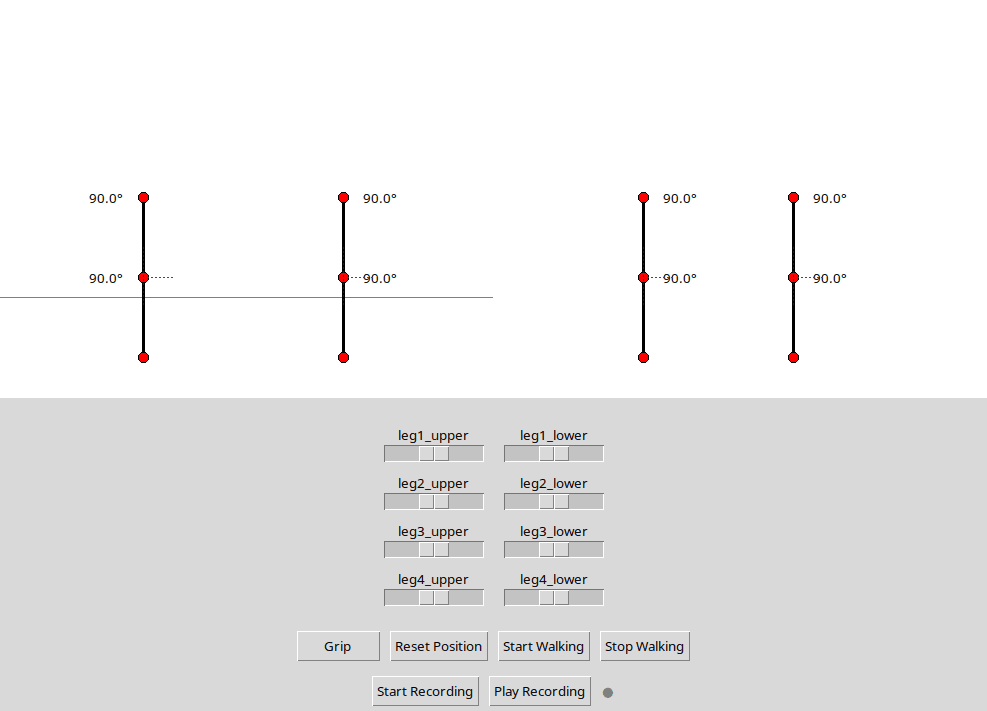
The GUI doesn't draw a cartoon — it solves the actual joint positions of all four legs in screen space:
def calculate_joint_pos(self, base_x, base_y, angle, length=80):
    rad = math.radians(angle)
    x = base_x + length * math.cos(rad)
    y = base_y + length * math.sin(rad)
    return x, y
Each leg's hip is fixed, the knee is hip + leg_upper at the upper-leg angle, and the foot is knee + leg_lower at upper + lower - 90 (crucially, the lower leg hangs off the end of the upper leg, not from the hip — the single most common bug in leg animations). A debug overlay draws the perpendicular reference lines and live angle labels, so the numbers on screen are the angles the controller will actually command — no snazzy UI hiding a wrong model.
Two interaction paths tune it:
- Sliders per joint (0–180°), which mutate the model and publish instantly.
- Drag — grab any joint (line 10 px pick-radius) and move it; the leg chain recomputes and republishes as you drag.
Gaits as data: record and playback
The GUI has a recording button. It captures a stream of joint frames into recorded_frames while you hand-drive a pose sequence (push a leg up, slide it forward, set it down), then replays them in a loop as a walking cycle. This is the design decision that made the whole project feel small:
- Record the pose sequence live.
- Play it back and watch the robot walk the same motion on repeat.
- Edit mechanics after — or a single sloppy joint — by recording again, not by editing code.
There's also a Grip macro and Start/Stop Walking toggles, reserving two servos for a pickup gripper so the robot can eventually do more than march: it was designed as the recovery half of the litter system, the piece that walks up to an object the drone found.
What actually had to be engineered
The GPIO bookkeeping was the unglamorous load: four stepper pins with an 8-step coil sequence, eight servos at 50 Hz on dedicated pins, and the multi-servo command that needs to be parsed without dropping a beat in the ROS chain. The reward for doing it as real hardware-driver code instead of one-off scripts is that the same protocol node eventually served the record/playback GUI and the autonomous path.
The takeaway that stuck: a walking robot is a gesture library. Build the recording loop before the perfect gait, and the perfect gait is free.
Related Project Case Study
ROS2 Quadruped — Stepper Drive + 8-Servo Legs, Tunable From a Tkinter GUI
Built the ground half of the litter-recovery system: a Raspberry-Pi-based quadruped controlled by ROS2 packages, with 4-leg × 2-joint servos plus steppers, and a Tkinter GUI that draws the robot from forward kinematics, lets you drag joints, and records/replays walking sequences.