
Shadow Stalker: Finding a Boat in the Arctic With a Drone Fleet
How we reverse-engineered a live Gazebo + ArduPilot Arctic simulation and built a fleet-wide search system — a three-stage vision engine, pixel-to-GPS trigonometry, a pan/tilt tower watch, and a fixed-wing-to-quad handoff — to find a moving vessel without ever touching the simulator's ground truth.
At a glance. At Hack the North, we built Shadow Stalker for the ArcticSim challenge: a fleet-wide search system that finds a moving vessel in the Bellot Strait, at 72°N. It combines a three-stage vision engine, pixel-to-GPS trigonometry, a pan/tilt tower watch, and a fixed-wing-to-quad handoff. We won the Dominion Dynamics sponsor track.
The setup
Dominion Dynamics shipped a challenge called ArcticSim: drop into a live Arctic simulation at Fort Ross, on the Bellot Strait in Nunavut, and take control of a heterogeneous fleet. A fixed-wing aircraft, a quadcopter, two pan/tilt antenna-tracker masts, a rover, a boat. All running ArduPilot, all speaking MAVLink, all inside a Gazebo Classic.
"Your job is to write the shared intelligence that coordinates them — detect, classify, and track a moving target vessel across contested terrain. You're scored live on coverage, collaboration, efficiency, and tracking accuracy."
The team: me on infrastructure and integration, Leonardo Zhou on the vision engine, Ari Khan on trajectory estimation and tactical planning, Riyan Kassam rounding it out.
Recon wins hackathons
The prompt told us to read the README, the docker-compose.yml, the .env.example, and the source tree. But these did'nt contain all the info, so before writing a line of autonomy, I cloned the real upstream arctic-sim repository and measured everything against the running sim. The result was RECON.md, and it became the team's source of truth for the rest of the event.
It's tempting to skip this and go straight to the detector. But almost every hour we didn't lose later, we bought in those first few hours.
Topology. A docker compose stack on a 10.23.0.0/24 bridge, run locally at 127.0.0.1. No ROS. Gazebo Classic plus gzweb, plus one ArduPilot SITL instance per vehicle.
| Asset | MAVLink endpoint | Sysid | Camera |
|---|---|---|---|
| quadcopter | udpout 127.0.0.1:14550 | 1 | :8600 — 960×720, 114.6° HFOV |
| fixed-wing | udpout 127.0.0.1:14560 | 2 | :8610 — 1280×720, 69.0° HFOV |
| tower-1 | udpout 127.0.0.1:14580 | 4 | :8630 — 1280×720, 60° HFOV |
| tower-2 | udpout 127.0.0.1:14590 | 5 | :8640 — 1280×720, 60° HFOV |
Two importent things to note: The MAVLink endpoints are udpin listeners — they stay mute until you transmit, so you open udpout and send first. And stranger: SITL only steps the simulation while a ground control station is attached. Our connections weren't just reading telemetry, they were what made the physics run. Open a socket and the world moves; close it and it freezes.
The camera numbers matter too. The slides quoted 640-wide video; the actual sensor SDFs were 960×720 and 1280×720. Field of view is what turns a pixel into a ray, so a 114.6° camera and a 60° camera are very different instruments.
Then the quirks, which I'd frame:
MAV_CMD_DO_REPOSITIONreturnsMAV_RESULT_UNSUPPORTEDon the copter — goto has to streamSET_POSITION_TARGET_GLOBAL_INT.- The quadcopter's "gimbal" is fake.
MNT1_TYPE=0, the SDF joint is fixed, and nothing moves it. It's a camera bolted 20.0° down. - Tower servos clamp to 1100–1900 µs, not the usual 1000–2000.
- The tracker's
ATTITUDEis not the camera's orientation — derive pointing from the PWM you commanded. - gzweb fragments large WebSocket frames; reassemble
FIN=0continuations or your JSON truncates at 16 KB. - After a reset the EKF takes one to two minutes to settle. The autopilot accepts
armandNAV_TAKEOFF, holds the motors at idle, and auto-disarms. It looks like a rejected takeoff. It's just patience. - World axes are EPSG:3413 polar-stereographic metres, not true east-north-up. Grid north is 49.8° off true north at this site.
That last one is worth dwelling on. If you treat world +y as north, every bearing you compute is rotated by almost 50°. The convergence angle, projection parameters, and site centre all had to be reverse-engineered from the sim's own maths. The site is also a 6.5 km square, not the 25 km × 2 km the prompt claimed. Trust the sim.
arcticlib: the boring layer that made the weekend possible
Once I knew the environment, I built a shared Python package called arcticlib and made everyone code against it. Nobody should have to think about MAVLink sockets, camera polling, or coordinate frames again — they'd call fleet.plane.goto(...) and move on.
Three decisions did most of the work.
Threads, not asyncio. pymavlink is blocking. Each vehicle owns exactly one background reader thread, and that thread is the only consumer of its socket. It keeps a lock-protected telemetry snapshot and appends a Pose to a ring buffer covering the last 30 seconds. Commands are sent from the caller's thread, confirmed by COMMAND_ACK, and routed to the reader through a condition variable. Nothing raises into a control loop; a failed command returns False.
One clock. The most important decision in the project. The sim has its own clock, published by gzweb on ~/world_stats. If a camera frame is timestamped in wall time but the vehicle pose is in sim time, a boat at pixel (640, 400) gets geolocated against a pose from a different instant — and at 20 m/s that's a metre of error per 50 ms. So every frame and pose carries the same t_sim, and fleet.pose_at(asset, frame.t_sim) interpolates the pose to the exact instant the frame was captured. Geolocation, temporal association, and fusion all depend on that alignment.
Dev and prod, separated by a wall. The ground-truth stream exists. We used it for exactly two things: labelling training data offline, and scoring our own accuracy during development. It lives behind ARCTICSIM_DEV=1, refuses to construct without it, and the autonomous mission never imports it. That discipline is what let us evaluate honestly without accidentally cheating.
The data contract stayed small and stable — Pose, Frame, Detection, Battery, AssetStatus — so Leonardo's detector could be swapped in behind my pipeline without either of us touching the other's code.
The pipeline
  tower-1 ──┐  pan/tilt sweep, CV, triangulate
  tower-2 ──┘        │
                     │  tip (lat, lon, sigma)
                     ▼
  fixed-wing ── 3-tier strait patrol ── 3-stage CV ── pixel→GPS ── fused fix
                     │                                              │
                     │                                              │  handoff
                     ▼                                              ▼
  quadcopter ── transit ── hold standoff ── refine fix ──► track API
Two aircraft, two jobs. The glider searches wide and gets a first fix. The quad flies to that fix, holds a standoff, and tightens it. The two tower masts act as a third, always-on sensor that can tip the glider onto a contact. Every fix that survives goes to the competition's track API as a named lat/lon with heading and speed.
Turning a pixel into a latitude and longitude
A pixel is not a point — it's a direction. To geolocate it you cast a ray from the camera through the pixel, rotate it into a local north-east-down frame, intersect it with the ground, and convert the horizontal offset to lat/lon with a WGS84 geodesic.
From resolution and field of view, the pinhole intrinsics are:
fx = (width  / 2) / tan(HFOV / 2)
fy = (height / 2) / tan(VFOV / 2)
cx = width / 2      cy = height / 2
A pixel (u, v) becomes a camera-frame direction (x right, y down, z forward), then a fixed axis remap into the body frame, because the optical axis points out the nose:
d_cam         = [ (u - cx) / fx, (v - cy) / fy, 1 ]
R_cam_to_body = [[0, 0, 1], [1, 0, 0], [0, 1, 0]]
Then the fixed mount pitch and the airframe attitude. Body is forward-right-down, NED is north-east-down, and MAVLink's ATTITUDE uses exactly the signs we need, so yaw, pitch, roll go straight in:
d_body = Ry(gimbal_pitch) @ d_cam
d_ned  = Rz(yaw) @ Ry(pitch) @ Rx(roll) @ d_body
Intersect with flat ground at height h below the camera:
dz = d_ned.z
if dz <= 0: no hit (at or above the horizon)
t = h / dz
north = t * d_ned.x
east  = t * d_ned.y
depression = atan2(dz, hypot(d_ned.x, d_ned.y))
Finally north/east become a bearing and ground range, and a forward geodesic on the WGS84 ellipsoid turns that into a latitude and longitude. That's the whole trick — and it's what makes a camera a range sensor.
The mount angle, and why it dominates everything
There's a term the simulator never tells you: the camera's fixed downward tilt. The quad is bolted 20.0° down, the wing 8.021° down, read from the sensor SDFs dumped live from gzweb. The wing's value comes from a quaternion (x=0, y=0.069942847, z=0, w=0.997551) — a pure rotation about body +Y of 2·atan2(0.069942847, 0.997551) = 8.021°.
At shallow depression, that angle is everything. Ground-range sensitivity to depression is:
dr/dδ = −h / sin²δ
At 45° down, a degree of error moves the fix by roughly h — negligible. At the glider's typical 8°, it moves it by tens of metres. That sin²δ denominator is why the entire error budget lives at the bottom of the frame.
We validated against ground truth over a 300-frame follow-ship run. At the SDF value of −8.021°, the median error was 79 m. Searching one degree of mount pitch on half the frames and confirming on the other half put the optimum at −8.50°, dropping the median to 38 m. A half-degree correction — probably because the detector locks onto the red hull's centroid, not the model's origin. The error fell off exactly as predicted:
| Depression angle | Median error |
|---|---|
| 20–40° | 13 m |
| 12–20° | 30 m |
| 8–12° | 47 m |
| 4–8° | 101 m |
| 0–4° | 190 m |
Uncertainty is a first-class output
Every fix ships with an error radius, because a range estimate without a confidence is useless to a planner. Four terms combine in quadrature: the depression sensitivity (h/sin²δ · σ_attitude), an altitude term (cot δ · σ_altitude), a lateral yaw term (range · σ_attitude), and the input position error. Defaults are 0.5° attitude, 3 m position, 2 m altitude.
Rays shallower than 10° are flagged grazing — where the flat-ground assumption and the error model both degrade fastest. The system can drop them or keep them and let fusion down-weight them. On the validation run the predicted 1σ radius tracked reality honestly: 63 m predicted against 79 m actual. A confidence interval that admits how wrong it is beats one that doesn't.
The one assumption worth naming is flat ground. There's no elevation model in the loop, so over rising terrain the fix biases long. I left a single seam — intersect_ground — where a terrain ray-march would drop in. Over the sea, where the boat lives, flat is exact.
The three-stage vision engine
Leonardo built this, and it's what let us see a boat that starts as a handful of red pixels against blue water and white ice.
The obvious move is YOLO. We didn't. The target is sub-pixel at long range, blended toward pink by the water; we had no labelled dataset and no time to build one; and we needed 3 Hz per camera across four sensors. A general detector is the wrong tool when your object has one distinctive property and your background is two colors.
Stage 1: color anomaly
We score every pixel with four cues: LAB redness (a* sits near 128 for neutral, ~140–200 for the boat), HSV red in both hue bands at once, direct contrast (R − max(G, B)), and a Mahalanobis distance against a background color distribution fitted from a downsampled frame. The combined map is thresholded, morphologically closed, and passed to connected components, then filtered by area and aspect ratio.
That's a candidate generator, not a classifier. It finds red things. Some red things are not boats.
Stage 2: the patch verifier
A small CNN looks at a 48×48 patch around each candidate and answers one question: boat, or not a boat?
The architecture is deliberately tiny — about 150k parameters, three convolution blocks (3→32→64→128) each with batch norm, ReLU, and max-pool, then global average pooling and a two-layer classifier with dropout. Inference is under 2 ms for a batch of 20 candidates on CPU. It trains in seconds and can't overfit data we don't have.
Which raises the problem: how do you train a boat classifier with no labelled boat data? You use the simulator's ground truth — offline, for labelling only. We recorded datasets where each frame carried the true vessel position projected into the image, ran Stage 1, and auto-labelled: a candidate near the ground-truth pixel is a positive, one far from it is a hard negative, and a boatless frame yields all negatives. That's exactly the data that matters — shoreline glints, ice edges, reddish shadows. A synthetic bootstrap generator (random water/ice backgrounds with a drawn red hull) let training start before any flight data existed.
The payoff: the CNN cut Stage 1's false positives by roughly 97%. On a ground-truth dataset, the merged pipeline produced one fused ship track of 244 hits over 190 frames at a mean score of 0.76.
Stage 3: persistence, and fusion
A single frame can lie; a boat that's real is in the same place next frame. Stage 3 maintains tracklets, associates candidates within a pixel (or geographic) gate, smooths with an exponential moving average, and confirms only after enough hits. The glider needs six to confirm; the quad only three, because by then we know roughly where to look.
Then we fuse the per-frame geolocated estimates into a single target with an inverse-variance weighted mean:
w_i   = 1 / error_radius_i²
mean  = Σ w_i · position_i / Σ w_i
sigma = 1 / sqrt(Σ w_i)
A grazing-angle frame with a 190 m radius contributes almost nothing; a clean 45° frame dominates. Clusters form greedily, most-certain-first, with a gate that scales with uncertainty but is clamped so two targets never merge.
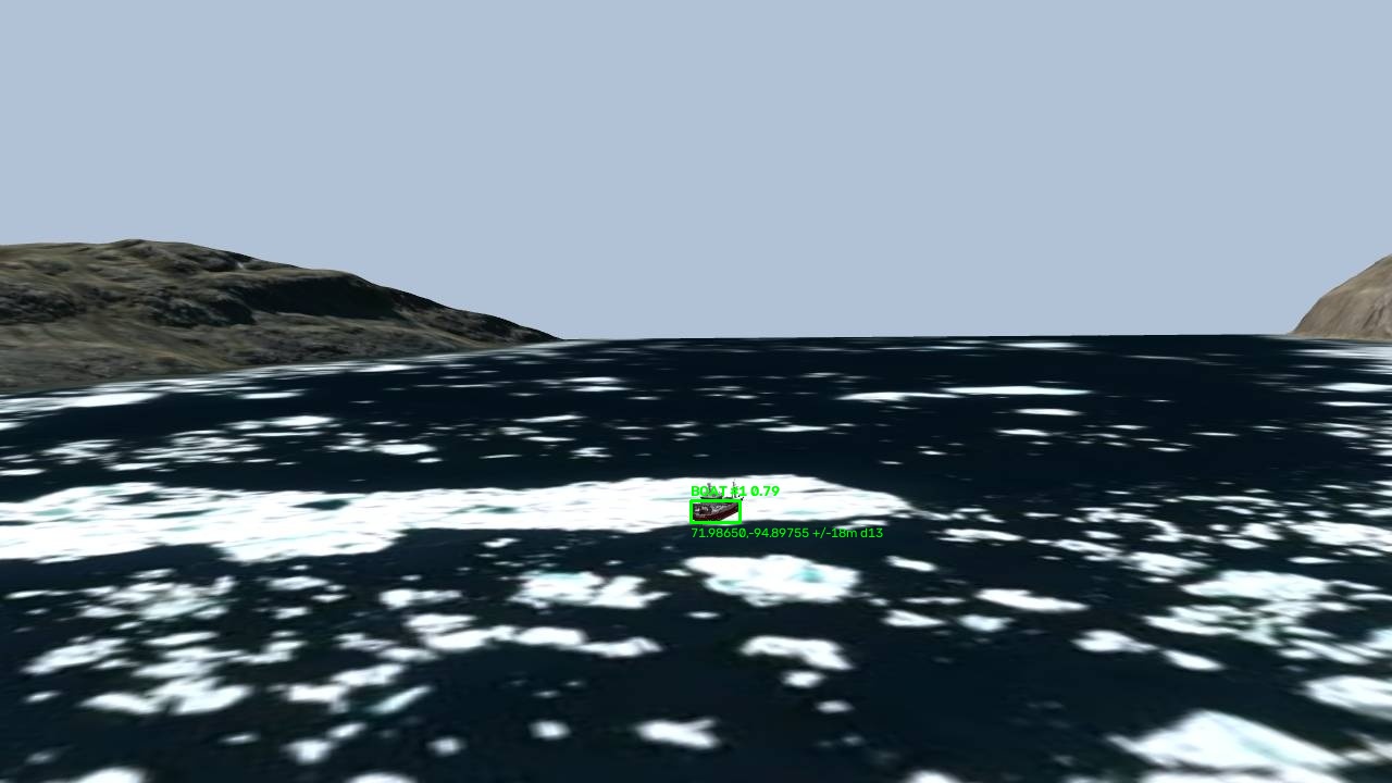
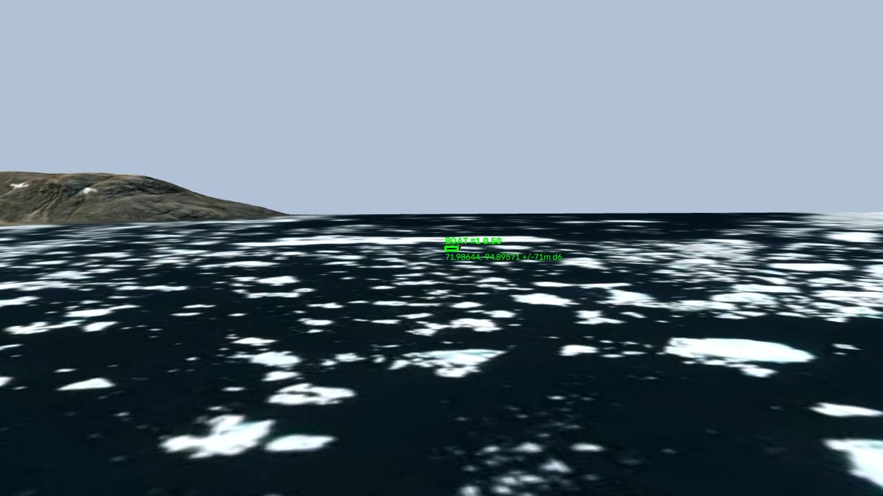
One caveat: the fused radius assumes per-frame errors are independent, so over hundreds of frames it collapses toward a metre even when a systematic bias remains. Use the per-frame ground-truth error to judge absolute accuracy, not the fused radius.
The tower watch: two static masts as a search sensor
The antenna-tracker towers were the asset everyone else ignored. They can't fly or move their mast — only pan and tilt a camera head. But they sit on high ground with a 60° field of view and never run out of battery, which makes them a permanent search sensor if you're willing to write the software.
It sweeps. Each mast pans back and forth across the strait in a serpentine raster of tilt levels. The pan step is 15°, well under the 60° HFOV so columns overlap; tilts step from −3° to −14° so near and far water are both sampled. At each dwell the servos settle and we run the same detector the aircraft use.
It geolocates. A tower's ATTITUDE is not its camera orientation, so we build an effective pose from the commanded pan and tilt — bearing baked into yaw, elevation into pitch — and feed it to the same pixel-to-GPS maths. Getting the bearing right meant working out that world yaw t bears convergence + 90 − t from true north. We verified it live: commanding the azimuth that should centre the true ship landed it at pixel (640, 360).
It triangulates. One mast gives a bearing line, not a point. Two masts seeing the same boat intersect to a fix. In local ENU, a ray on bearing b is p + t·(sin b, cos b), and the two-ray intersection is a cross product. We reject near-parallel crossings (under 8°, where error explodes) and intersections behind either sensor, and estimate uncertainty as max(t1, t2) · σ_bearing / sin(cross).
A confirmed contact becomes a tip the glider diverts to. If the glider finds nothing, the tip goes dry after 45 seconds and the patrol resumes. A sensor network built out of two things that were never designed to be one.
The mission, as a state machine
main.py runs a complete mission with no arguments. Two state machines run side by side.
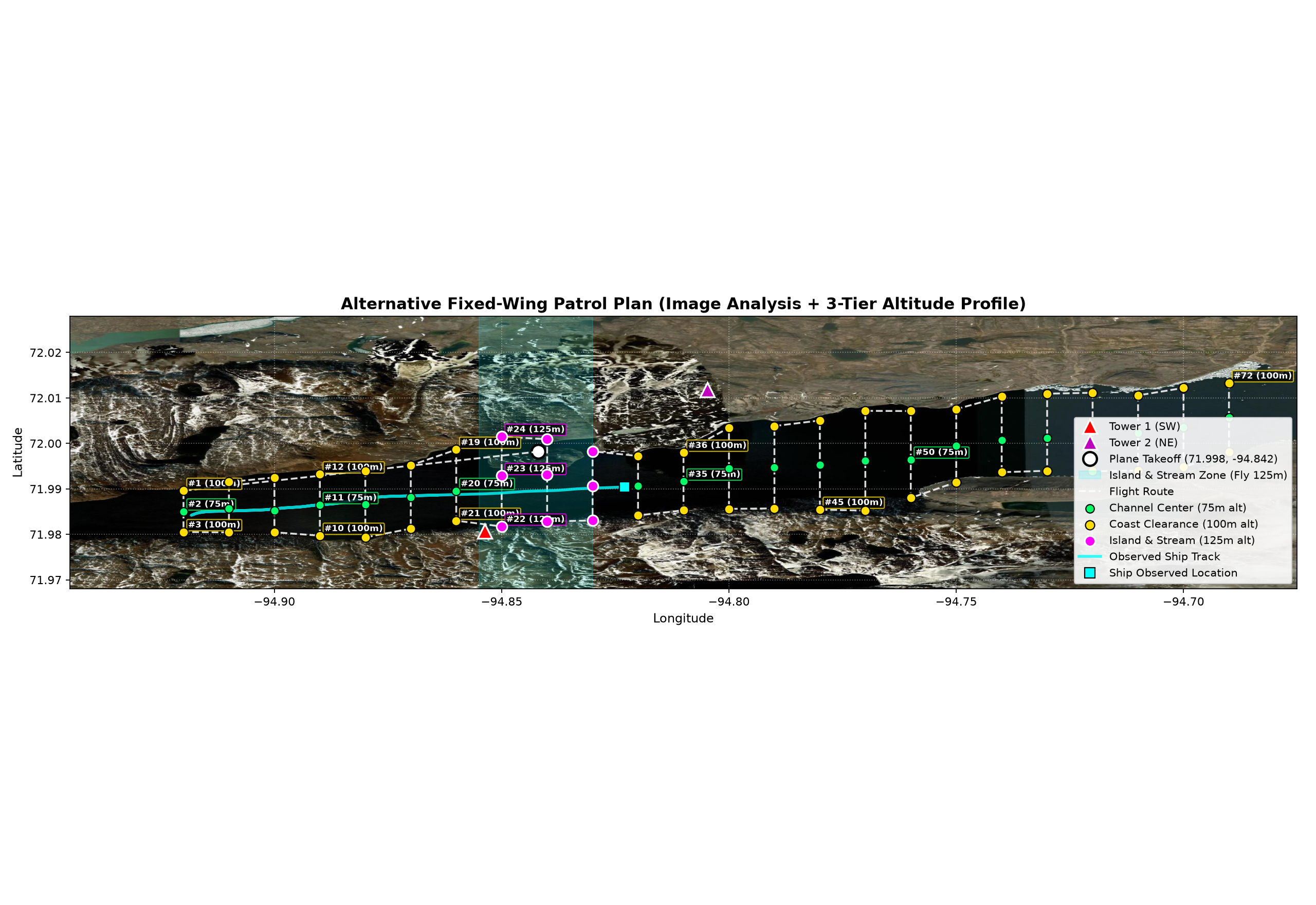
The glider moves CLIMBING → SEARCHING → TRACKING. It flies a patrol derived from satellite imagery — a 3-tier altitude profile at 75 m over the channel centre, 100 m over the coast clearance band, and 125 m over the island and stream zone, with a 120 m safety margin from a hand-built coastline profile. The moment a boat is confirmed, it starts tracking.
The quadcopter moves ON_GROUND → TAKEOFF → TRANSITING → SEARCHING_FOV → TRACKING / HOVER_IDLE. It films the pad from t=0 so both feeds align chronologically, takes off the instant the glider confirms a sighting, transits to the fix, and starts its own search. If the glider refines the location mid-transit by more than a metre, the quad adopts it immediately.
The detail that makes the glider useful is the overflight re-attack. A fixed-wing can't hover, so loitering leaves the target outside the frame half the time. When the target is far, the glider aims at a point 250 m past the boat along the approach bearing — flying straight over, wings level, target centred. Overhead, it extends 350 m along the strait axis to set up the next clean pass. If contact is lost for eight seconds it falls back to a figure-8 search around the last fix (400 m along the strait, 160 m lateral), then rejoins the patrol.
The standoff, and why 45°
The quad doesn't fly directly over the boat. Its camera is fixed 20° down and can't be pointed, so overhead would leave the target out of frame. Instead it holds a standoff:
standoff = altitude / tan(view_depression)
At 25 m altitude and 45° depression, that's a 25 m hold point, placed on whichever side the quad is, yaw aimed back at the ship. Why 45°? Because of the h/sin²δ curve. The quad's vertical FOV is 98.9°, reaching ~69° of depression at the bottom of its frame — far steeper than the glider's 8°. The geometry is simply better, and that's why the split works: the glider finds, the quad refines.
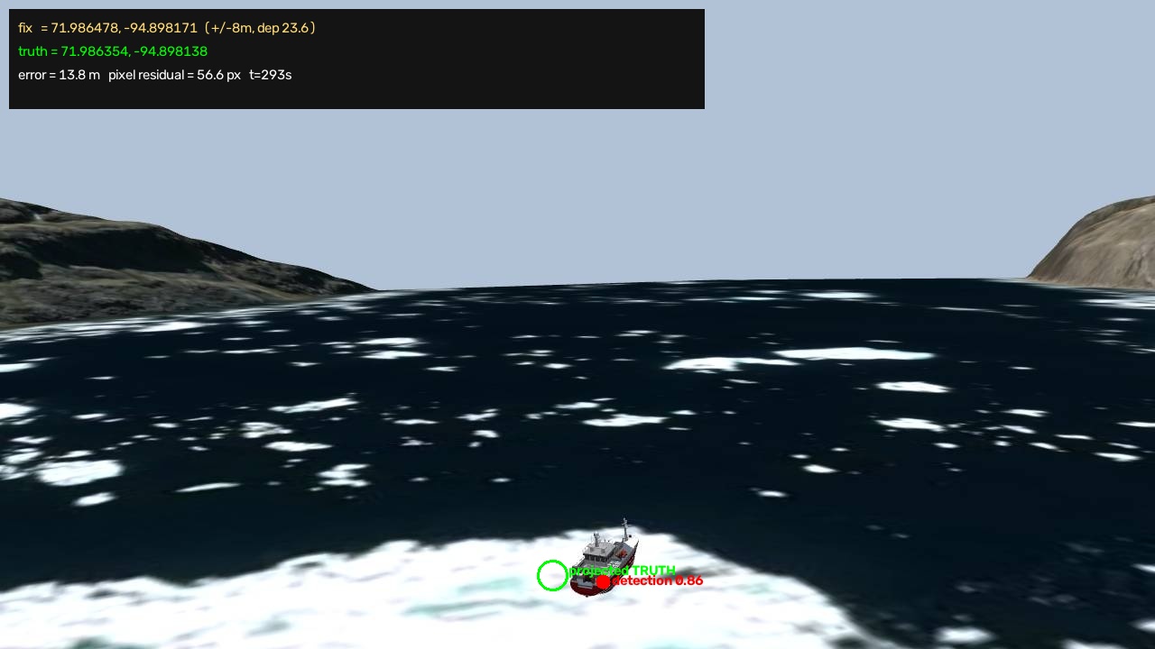
Measured end to end: the glider found the vessel and the quad refined the fix to a 12.4 m median error, 2.2 m at best.
The boat tracker and the tactical tether
Ari built a causal Kalman filter for the vessel's trajectory — six states (position, velocity, acceleration in x and y), a constant-acceleration transition model, and a white-noise-jerk process model, with the Joseph-form covariance update for numerical stability. It handles sparse GPS and is causal by design: no future samples, because a live system doesn't get any. A causal cubic spline smooths the estimate without look-ahead.
He also wired a small local LLM as a tactical supervisor. A local Ollama model (llama3.2:1b) receives a system prompt forcing a strict JSON action schema — CLOSED_ZONE, INTERCEPT, or ABORT, each with coordinates, a radius, and a reason — for edge-case calls like closing an exclusion zone after a reported attack. The patrol planner then reroutes around any closed zone with tangent detours.
Reporting to the track API
Every surviving fix goes to the competition's track endpoint: POST a name and lat/lon and it creates a track; POST the same name and it updates, bumping a fix counter. We derive heading and speed from the previous fix so the track carries motion, not just position.
We rate-limit ourselves hard, because the endpoint throttles: at most one request per second globally, and per track one every five seconds and only if the target moved more than five metres. On HTTP 429 the client honours Retry-After and backs off exponentially. Being polite to the scorer's API is not the place to be clever.
Everything that broke
The cloud sim died. The hosted simulation broke down partway through and we moved the entire stack local. That's a day of a weekend, gone — and why RECON.md insists on 127.0.0.1 and the host is configurable.
The quadcopter stopped translating. It would arm, take off, climb, and hover, but goto wouldn't move it horizontally. Vertical control worked; horizontal didn't. We chased it as our bug before concluding it was sim-side: SERVO_OUTPUT_RAW showed hover throttle while the model stayed put. You can't fix someone else's physics in a weekend, so we retried and moved on.
The EKF settle time. Already mentioned, but it cost real debugging hours before we understood it. The autopilot accepts takeoff, holds the motors idle, and auto-disarms. The fix was to loop: if it disarms without climbing, re-arm and try again until the timeout is spent.
The gimbal that isn't. We spent time trying to command a camera with no command surface. Both mount types fail pre-arm and mount commands move nothing. Verify a capability exists before building on it.
What we ended up with
tools/smoke_test.py— 23 end-to-end checks against a live sim, all passing.- Tower calibration verified through
SERVO_OUTPUT_RAWwith zero servo-tracking failures. - Geolocation: 38 m median at the calibrated mount, with an honest uncertainty estimate.
- Detection: one fused ship track of 244 hits over 190 frames, and a CNN that removed ~97% of false positives.
- Two-step mission: 12.4 m median, 2.2 m best.
- A complete mission video, exported as three files — glider feed, quad feed, and a synchronized stacked cut.
Running it is one command once the sim is up:
# Verify the fleet against a live sim (add --no-fly to skip flight commands)
python tools/smoke_test.py

# Full mission: tower watch + glider search + quad follow + video export
python main.py --search-timeout 180 --quad-duration 90
A bare python main.py is a complete mission. With ARCTICSIM_DEV=1 the glider auto-chases the live vessel for testing; otherwise it flies the safe 3-tier patrol.
The whole system is open source: github.com/malekhammoud/Drone-Sim.
What I'd tell someone doing this next
Recon before code. The most valuable file in the repo just says what's true about the environment. Every quirk you measure instead of guess is an hour you don't lose later.
One clock, or none of it works. If your sensors don't share a timebase, nothing downstream is correct.
Make the interface boring. arcticlib existed so three people with different specialties could work in parallel without merge pain. The dull interface is what let the interesting parts be interesting.
Uncertainty is a feature, not a caveat. A fix without an error radius is a guess wearing a coordinate's clothing. Once every detection carried a sigma, the planner could reason about which to trust — and fusion practically wrote itself.
Don't use ground truth in the loop. It's the easiest way to win a benchmark and the fastest way to build something that doesn't work.
Ship the demo. Two feeds, chronologically aligned, stacked into one video, made the whole system legible to someone who wasn't there. If you can't show it, it didn't happen.
We went into this with no swarm experience and came out with a fleet that finds a boat in the Arctic, without cheating, and tells you how sure it is. That's the whole story.