
The Anatomy of a Drone: Understanding the Key Components
An engineering breakdown of the subsystems that make an autonomous multirotor work — and the key architectural split between a flight controller and a companion computer, with real numbers from a litter-mapping build.
Introduction
A multirotor is a fundamentally unstable system. There is no geometry or material that keeps it level — it stays in the air purely because a microcontroller reads an inertial sensor and adjusts four motor speeds tens of times per second. Understanding drones is really understanding this feedback loop and every subsystem feeding it.
Here is the breakdown, in the order the power and data actually flows:
- Batteries
- Propellers & Newton's Third Law
- Electronic Speed Controllers (ESCs)
- Power Distribution (PDB)
- Flight Controller
- The Companion Computer Split
- GPS
- IMU & Magnetometer
- Radio Link & Telemetry
1. Batteries
The modern drone exists because of Lithium Polymer chemistry: high energy density with high discharge rates.
- Capacity (mAh) — total charge stored.
- C-Rating — the safe continuous discharge multiple. A 1000 mAh @ 30C pack can deliver 30 A before the pack sags.
$$\text{Max Current} = 1.0\ \text{Ah} \times 30 = 30\ \text{A}$$
That burst capacity is what lets a motor spin up fast enough to arrest a gust mid-swing. Sag under load is the silent killer of flight times — measured volts under load, not resting volts.
2. Propellers
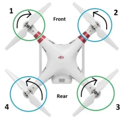
A propeller moves air. Lift comes from the pressure differential created by the moving blade, and a common misconception is that all four rotors spin the same way. They don't: diagonally paired motors counter-rotate (Motor 1 & 3 one way, Motor 2 & 4 the other). By Newton's Third Law every spinning prop exerts reaction torque on the frame — pairing directions cancels net yaw torque in hover. Differential motor speed then produces controlled yaw without changing altitude.
3. Electronic Speed Controllers (ESCs)
The ESC is the power bridge between logic and muscle. It takes DC battery voltage and chops it into three-phase AC pulses for a brushless motor, switching MOSFETs at high frequency according to PWM or DShot commands from the flight controller. On a research build, motor commands loop at hundreds of hertz; everything downstream — ESC, prop, frame — responds within a few milliseconds or the attitude loop destabilizes.
4. Power Distribution (PDB)
The PDB splits main battery voltage to each ESC and steps regulated 5V/12V down to the flight computer, cameras, and add-ons. On a DIY build, inductively isolated rails matter: motor current transients can inject enough noise to reset a precision device sitting on the same bus.
5. Flight Controller
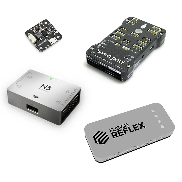
The flight controller is the computational brain. It samples the IMU at 400 Hz–1 kHz and runs a PID control law on roll, pitch, and yaw, commanding exact motor speeds dozens of times per second. Research-standard examples are the Pixhawk series running open-source ArduPilot or PX4, which layer waypoint navigation, failsafe return-to-launch, and sensor fusion on top of that stabilization core.
6. The Companion Computer Split
The most important design decision on our litter-mapping drone was not letting the flight controller do everything. Two very different types of computation are required:
- Hard real-time attitude stabilization at 400 Hz — the Pixhawk's job.
- High-level autonomy — computer vision, GPS waypoint grids, camera-to-telemetry synchronization — which needs a full Linux environment.
So a Raspberry Pi 4B joined the build as a companion computer, linked to the Pixhawk over a hardware UART with DroneKit/PyMAVLink. The same pattern (FC + companion) is how Pixhawk-based research drones, hobby autonomy kits, and even some commercial platforms are structured. The serial link does not need speed — it needs determinism, which is why we chose a wired UART over a USB adapter.
7. GPS
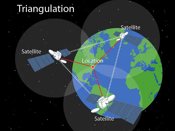
GPS gives 3D position (latitude, longitude, altitude) by measuring light-time from at least four satellites, enabling waypoint grids, geofencing, and position-hold. It is not precise enough to fly close to things — a consumer module on our build held roughly ±1 metre in loiter. The practical lesson: GPS is for where, not for how close.
8. IMU & Magnetometer
The IMU pairs a gyroscope (rotational velocity, °/s) with an accelerometer (linear acceleration, m/s²). Fusion filters (Extended Kalman, Madgwick) merge these complementary streams into a single roll/pitch/yaw attitude estimate. A magnetometer adds an absolute compass heading, which fixes the gyro's cumulative yaw drift — essential when waypoint missions depend on heading.
9. Radio Link & Telemetry
The RC link is the pilot's safety tether, but on an autonomous system the downlink carries telemetry and mission data. Modern 2.4 GHz frequency-hopping links and long-range ELRS/Crossfire (915 MHz) offer sub-10 ms control latency, while MAVLink-based telemetry streams let a ground station watch the mission live and take over in an emergency.
Conclusion
Every subsystem above is only a means to one end: a stable platform for something the flight controller can't do on its own. On the Autonomous Litter Detection and Recovery System, the companion computer ran a YOLOv5 detector that classified litter in drone footage at 90% accuracy while the Pixhawk held position, and the mission data was logged with GPS tags for cleanup crews. Understanding the FC/companion split — not any single component — is what made that possible.
Related Project Case Study
Drone Litter Mapping System
A full-stack outdoor robotics project: an ArduPilot F450 with a Raspberry-Pi companion flies GPS waypoint surveys, detects litter with YOLOv5 (90% accuracy), syncs camera frames to telemetry, and files every hit into a PostGIS-backed litter map. A ROS2 walking robot built for recovery rounds out the system, documented in a paper.